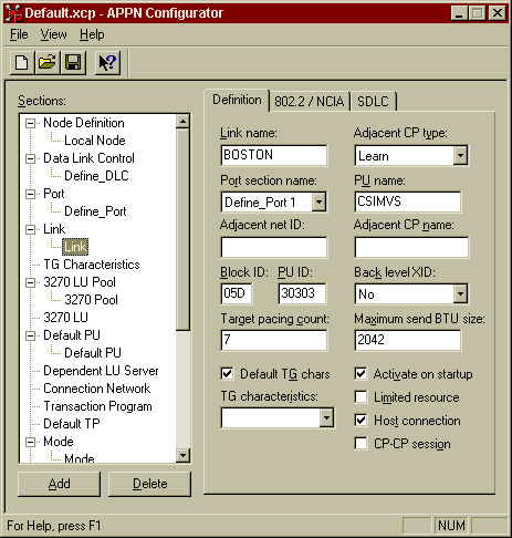
Select Link from the Sections window and then click the Add button.
- Enter the Link Name, enter a name to describe the Link definition which will be unique within this node. For example, use a name which will describe the remote node, i.e. the host system, which this Link is used to communicate with.
- Select Adjacent CP type, select Learn.
- Select Port section name, select the Port definition to associate with this Link, that is, the Port definition configured above.
- Enter PU Name, enter a name which will act as an internal PU name which will be uniquely associated with this Link. For example duplicate the Link Name for the PU Name.
- Enter Adjacent net ID, leave this field blank.
- Enter Adjacent CP name, leave blank.
- Enter the Block ID, PU ID, this is the 8 digit hexadecimal number which is used to identify this local system on the SNA network.. The first 3 digits is the block (IDBLK) number followed by the last 5 digits of the node (IDNUM) number. These numbers correspond with the IDBLK and IDNUM fields of the PU definition for this machine as defined in VTAM on the host system.
- Select Back level XID, choose the default, No.
- Enter Target pacing count, allow this field to default to 7.
- Enter Maximum send BTU size, select the maximum size of packet than the Link can send without segmentation. You must specify a value that is less than or equal to the value of the MAXDATA parameter of the PU definition in VTAM for this machine. For a 4 Mbs Token Ring specify a BTU value of 4195 or less. For a 16 Mbs Token Ring specify a value of 16393 or less. For an Ethernet LAN specify a BTU value of 1493 or less.
- Select Default TG chars check box.
- TG characteristics, leave blank.
- Activate on startup check box, we suggest that initially this be left unselected so that the Link is tested by starting manually. Once this is tested this option can then be selected.
- Limited resource check box, do not select.
- Select Host connection check box.
- CP-CP session check box, do not select.


