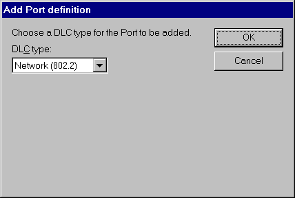
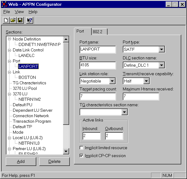
Select Port from the Sections window and then click the Add button. The Add Port definition dialog box will appear. Select DLC type Network (802.2) and press OK. The Port definition template will then be displayed.

- Enter the Port Name to describe the Port definition which will be unique within this node. For example, LANPORT since this is going to be a LAN connection.
- Select the Port Type, select SATF (shared access transport facility), the appropriate choice for a LAN connection. Note: select Switched for SDLC over a dialup line, Nonswitched for leased line SLDC or DFT.
- Enter the BTU size, select the maximum size of packet that the port can receive without segmentation. You must specify a value that is less than or equal to the value of the MAXDATA parameter of the PU definition in VTAM for this machine. For a 4 Mbs Token Ring specify a BTU value of 4195 or less. For a 16 Mbs Token Ring specify a value of 16393 or less. For an Ethernet LAN specify a BTU value of 1493 or less.
- Select the DLC section name, the definition to associate with this port, that is, the DLC definition configured above.
- Select Link station role, choose the default, Negotiable.
- Select Transmit/receive capability, choose the default, Half.
- Enter Target pacing count, allow this field to default to 7.
- Enter Maximum I-frames received, allow this field to default to 7.
- You may leave the TG characteristics section name blank.
- Enter Active Links. These parameters define the maximum number of connections or links which can be active using this port. This will define the maximum number of SNA connections to other nodes using this port, i.e. how many mainframes or peer systems you want to connect to using this port. We suggest you set both the Inbound and Outbound parameters to 2.
- The Implicit limited resource check box should be unselected.
- The Implicit CP-CP session check box should default to selected.


